
My first ESP32 voice speaker (esp32-jarvis) worked, but it had one problem I couldn’t engineer my way out of. As soon as music was playing, the wake word intermittently stopped working. The mic was hearing the speaker, and software echo cancellation on an ESP32-S3 simply isn’t good enough to reliably dig a voice out from under it. This build fixes that properly. It’s a Home Assistant Assist satellite that also plays music well enough to leave on in the kitchen, in a 3D-printed enclosure, for about £140.
The key decision: hardware echo cancellation
The heart of it is the Seeed reSpeaker XVF3800 with XIAO ESP32-S3. The XVF3800 is an XMOS voice DSP with a 4-mic array, beamforming and hardware acoustic echo cancellation (AEC). The XIAO ESP32-S3 runs ESPHome and talks to Home Assistant.
The one rule that makes or breaks this design: the amplifier must be fed from the XVF3800’s 3.5 mm line-out, not from the ESP32’s I2S. AEC works by subtracting what it knows it’s playing from what the mics hear. If the audio reaches the amp some other way, the DSP has no reference and you’re back to the jarvis problem. The same rule is why this can’t be a Bluetooth speaker. The ESP32-S3 only has Bluetooth Low Energy, not the Classic Bluetooth needed for A2DP audio, and bolting a separate BT receiver onto the amp would bypass the DSP entirely.
Parts list
some links are affiliate links which will earn me a small commission but will cost you no extra
| Part | What I used | Approx. cost |
|---|---|---|
| Mic array + MCU | reSpeaker XVF3800 with XIAO ESP32-S3 (The Pi Hut, case version) | ~£62 |
| Driver | Dayton Audio ND90-8 3.5″ full range (EU stock) | ~£36 |
| Amplifier | XH-M542 TPA3116 mono board (full range, not the “subwoofer” variant) | ~£10 |
| Power supply | 24 V 2.5 A brick | ~£14 |
| DC power socket | Panel-mount DC socket (fits the 11 mm hole in the base) | ~£7 |
| 5 V supply | Hi-Link URB2405YMD-20WR3 isolated DC-DC (9–36 V in, 5 V 4 A, isolated). Get the 2405 variant. Add a 100–470 µF / 16 V capacitor across its output | varies |
| Resistors | 2× 1 kΩ metal film (mono sum into the amp) | ~£5 |
| Audio lead | 3.5 mm stereo lead, right-angle plug (XVF line-out to amp) | ~£5 |
| Ground loop isolator | 3.5 mm ground loop noise filter (optional: only needed if you use a non-isolated 5 V supply such as an LM2596 buck; see “Hum and the ground loop” below) | varies |
| Grille cloth | Speaker grille cloth | ~£7 |
| Damping | Polyfill (15–25 g) and a felt pad | ~£7 |
| Fixings | M3 brass heat-set inserts | ~£5 |
| Screws: lid to head | M3 × 8 mm countersunk (DIN 7991), ×4 | ~£3 |
| Screws: head to chamber | M3 × 8 mm button or socket head, ×4 | ~£3 |
| Screws: driver to baffle | M3 × 8 mm button or socket head, ×4 | ~£3 |
| Screws: base to chamber | M3 × 28 mm, ×3 (or M3 × 30 mm with two washers under each head; a plain 30 mm bottoms out in the insert) | ~£4 |
| Screws: board to lid | M2 × 5 mm self-tapping pan head, ×3 (6 mm maximum, or it comes through the lid) | varies |
| Filament | Black and translucent PLA (lid), PLA (body) or PETG | varies |
Watch out for the amp. Many cheap TPA3116 mono boards on eBay are subwoofer boards with an NE5532 low-pass filter. They look almost identical. The one you want has no op-amp chip and no filter, just the TPA3116, the inductors and the screw terminals.
Choosing the driver
I modelled several 3–4″ full-range drivers in the same 1.8 litre sealed box before settling on the ND90-8. In a box this small, bass is decided by the driver’s resonance (Fs). The ND90 is unusually low for its size.
| Driver | Fs / Qts / Vas | Bass −3 dB in 1.8 L sealed | Verdict |
|---|---|---|---|
| Dayton ND90-8 | 70.7 Hz / 0.65 / 1.77 L | ~82 Hz | The pick |
| AuraSound NS3-193-8A | 80 Hz / 0.67 / 1.25 L | ~88 Hz | Near-identical, drops into the same baffle, but discontinued |
| Dayton DMA90-8 | 94 Hz / 0.57 / 1.7 L | ~118 Hz | Bass-light |
| FaitalPRO 3FE26-8 | 150 Hz / 0.79 / 0.9 L | ~147 Hz | Great for voice, thin for music |
| Visaton FRS 8 M | 125 Hz / 0.49 / 1.1 L | ~183 Hz | UK stock and cheap, but a kitchen radio sound |
The annoying part: the ND90 is hard to get in the UK at a sensible delivered price, and my first one was lost in transit from the Netherlands. I didn’t find a UK-stock driver that matches it.
I went sealed rather than ported on purpose. With a Qts of 0.65 the ND90 suits a sealed box, and a port tuned to 70 Hz in 1.8 litres would need to be about 148 mm long, which is longer than the chamber is tall. If the bass ends up too thin, the upgrade path is the matching ND90-PR passive radiator.
The enclosure
I designed the enclosure parametrically in OpenSCAD. It’s a Ø150 × 208 mm cylinder in five printed parts, from top to bottom:
- Lid: the XVF3800 hangs underneath it, LED side up, on its three M2 holes. Each of the four mic ports has a TPU gasket. It’s printed in two colours on the Bambu H2D. Most of the lid is black PLA, with a 0.4 mm (two-layer) translucent ring over the board’s 12 onboard LEDs, so the LED ring shows through as a halo. My first attempt at 1.6 mm was far too dim. Twelve thin black spokes between the LEDs hold the centre disc in place.
- Head: the electronics bay holding the amp and the isolated 5 V converter. It also has a printed plunger for the board’s mute button and a pinhole for reset, both through the side wall.
- Chamber: a 1.8 litre sealed box, with the baffle printed as its floor. The ND90 mounts from below and fires downwards. Print it with at least 6 walls so it’s airtight.
- Grille sleeve: a slotted printed ring, 83% open, that holds the grille cloth across the 360° gap below the chamber.
- Base: a concave deflector that spreads the down-firing sound outwards, with four struts and the DC jack.
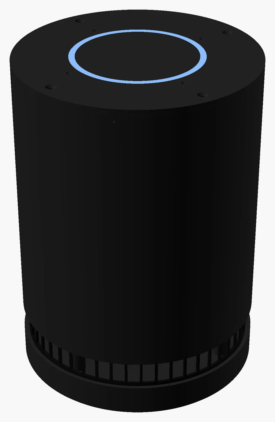
The finished design: Ø150 × 208 mm, with the LED halo in the lid
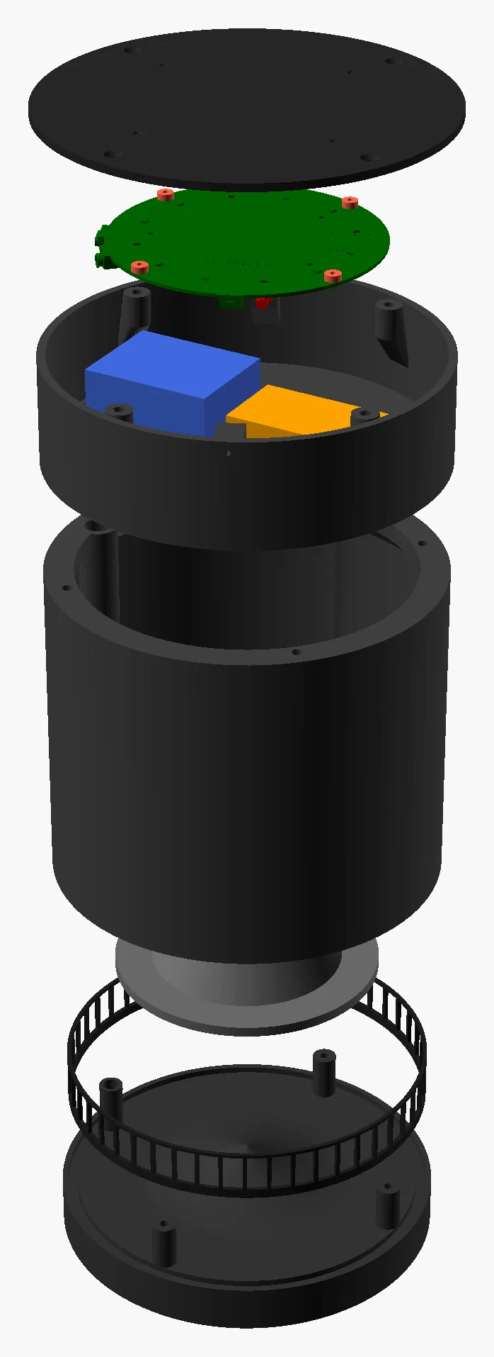
Exploded view, top to bottom: lid, XVF3800 board, head with amp and 5 V converter, sealed chamber, ND90 driver, grille sleeve, base
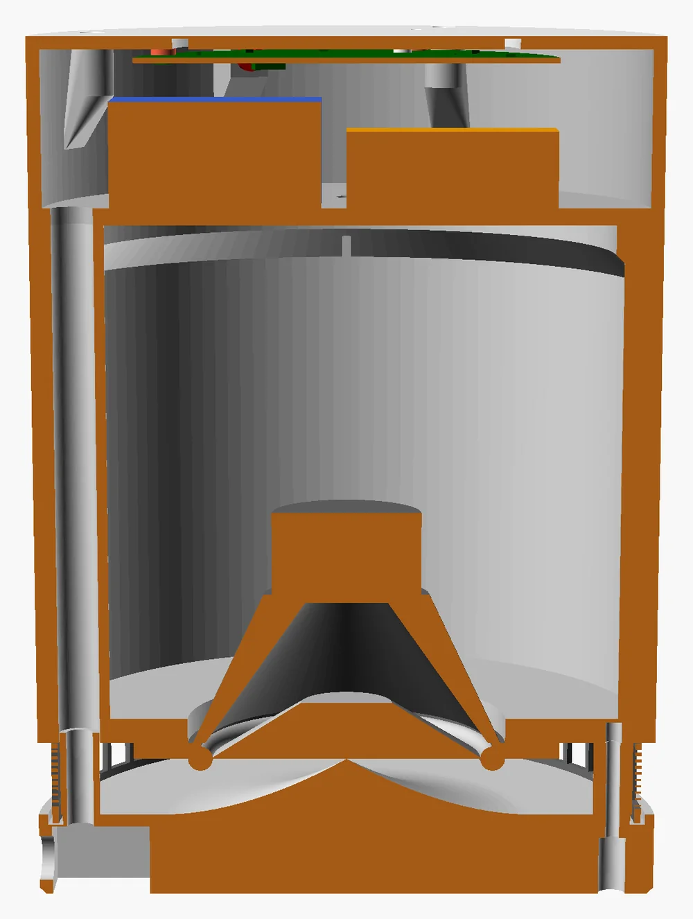
Cross-section: board under the lid, electronics bay, 1.8 L sealed chamber, down-firing driver over the deflector
I started from Seeed’s STEP model of the board, which turned out to be only partly accurate. The PCB outline, mounting holes and mic ports matched my board, but the connector and button positions didn’t match this board revision. I found both buttons by measuring with callipers from the lid’s screw holes, then solving for the angle. Two independent measurements agreed to within a degree, which is how I knew it was right. Lesson: trust the STEP model for the outline, and measure everything else.
Inside the chamber: 15–25 g of polyfill, loosely teased, plus a felt pad under the chamber’s top. That tames internal reflections and makes the box behave as if it were slightly bigger.
Wiring
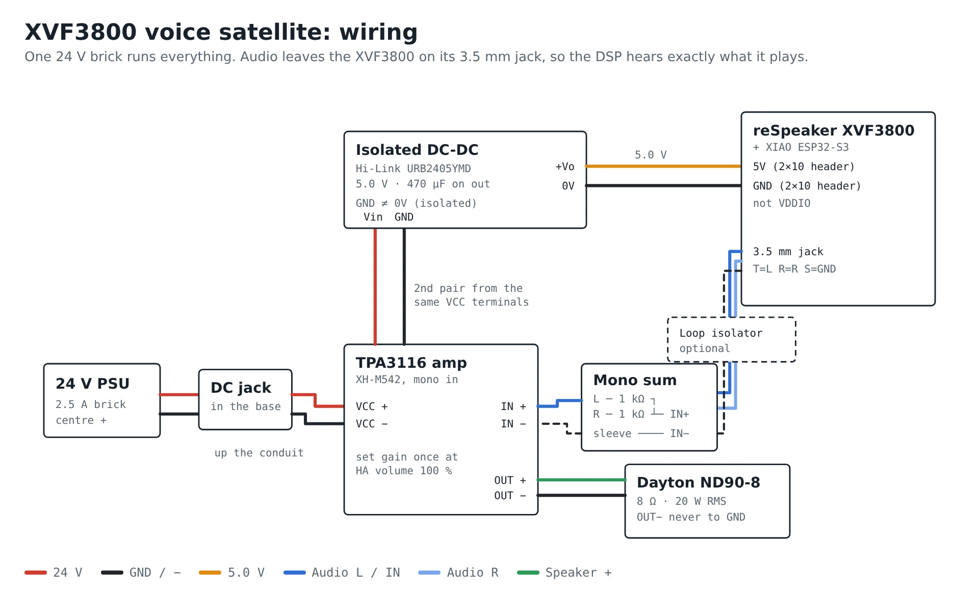
Full wiring: one 24 V brick, an isolated 5 V converter fed from the amp’s VCC terminals, and audio from the XVF3800’s 3.5 mm jack through a mono sum
Two cautions. First, at 24 V the TPA3116 can deliver around 35 W into 8 Ω, and the ND90 is rated at 20 W. Set the amp’s gain pot once, with Home Assistant volume at 100%, to just below the point where it sounds strained. Second, never plug USB into the XIAO while the converter is powering the board. The two 5 V supplies will back-feed into each other.
Hum and the ground loop
My first build used a cheap LM2596 buck converter for the 5 V rail. It worked, but there was an obvious hum through the speaker, and it got worse whenever the LED ring lit up. Re-routing cables made no difference. Two five-minute tests found it:
- Unplug the audio lead and short the amp’s IN+ to IN−. The hum disappeared, so it was coming in through the audio input, not from the amp itself.
- Power the XVF3800 from a USB power bank instead of the buck, with the amp still on 24 V. The hum disappeared again, even with the LEDs running. So the board’s own output was clean.
That’s a classic ground loop. A buck converter isn’t isolated, so its input and output share a ground. That gave the board and the amp two ground connections: one through the 3.5 mm lead’s sleeve, and one through the buck back to the amp’s power terminals. The LEDs draw pulses of up to about 0.7 A, and some of that return current took the audio route. The amp heard the tiny voltage that put on its input reference and amplified it as hum. The proper fix is to break the power-side link with an isolated DC-DC converter, which has no electrical connection between its input and output. That’s why the parts list uses the Hi-Link module. A 3.5 mm ground loop isolator in the audio lead also works and costs less, but cheap ones can soften the deep bass. I’d only use one if you’re sticking with a plain buck.
Assembly
Everything is held together with M3 screws going into brass heat-set inserts, so nothing threads straight into plastic except the three small M2 screws that hold the board. Fit all the inserts first, before any electronics are near the parts.
Where the 15 inserts go
| Part | Where | Qty | Fit from | Takes |
|---|---|---|---|---|
| Head | The top of the four lid bosses, just inside the rim | 4 | Above | M3 × 8 countersunk, down through the lid |
| Chamber | The four holes in the top lip, at 45°, 135°, 225° and 315° | 4 | Above | M3 × 8, down through the head floor |
| Chamber | The four holes around the driver cutout in the baffle (the underside) | 4 | Below (chamber upside down) | M3 × 8, through the driver frame |
| Chamber | The three holes near the edge of the baffle underside, where the base struts land (the fourth strut is the wire conduit and has no insert) | 3 | Below (chamber upside down) | M3 × 28, up through the base |
- The holes are 4.0 mm across and 5–6 mm deep. Use M3 inserts made for a 4 mm hole, 5 mm long or shorter.
- Use a soldering iron at about 220 °C for PLA (240 °C for PETG), ideally with an insert tip. Let the insert sink under its own weight with light pressure, keep it square, and stop when it is flush. Hold a flat piece of metal on top for a few seconds as it cools so it stays level.
- Check the driver holes before you fit those four inserts. They sit on a 94 mm circle. Put the ND90 against the baffle and confirm its holes line up. If yours differ, rotate the driver or open the holes slightly with a drill.
Build order
- Fit all 15 inserts as above.
- Driver into the chamber. Solder or crimp a pair of speaker wires to the ND90, about 25 cm long, and mark the red-dot terminal as positive. Feed the wires up through the chamber and out of the open top. Fit a thin foam gasket or weatherstrip around the cutout, then screw the driver to the underside of the baffle with 4 × M3 × 8, cone facing down. The joint must be airtight.
- Damping. Loosely tease 15–25 g of polyfill into the chamber. Don’t pack it against the back of the cone.
- DC jack into the base. Push the panel socket through the 11 mm hole at the back and tighten its nut from underneath; the pocket is open from below. Run its two wires, about 30 cm long, up through the rear strut.
- Grille. Wrap the grille cloth round the printed sleeve, folding it over the top and bottom rims, and drop the sleeve into the groove in the top of the base.
- Chamber onto the base. Thread the DC wires up through the conduit tube inside the chamber. Lower the chamber onto the struts; the spigot on the rear strut locates in the conduit. Fix it with 3 × M3 × 28 from underneath, through the counterbored struts. If you only have 30 mm screws, put two washers under each head or they will bottom out.
- Head onto the chamber. Push the mute plunger into its guide from the inside of the head first; its flange stops it falling out. Stick a felt pad to the underside of the head floor. Feed the speaker wires through the small hole in the head floor and the DC wires through the conduit hole, then sit the head on the chamber lip and fix it with 4 × M3 × 8 down through the floor.
- Seal the chamber. Put a blob of hot glue over the speaker-wire hole and round the top of the conduit. Any leak here costs you bass.
- Electronics. Hot-glue the amp and the isolated 5 V converter to the head floor; don’t screw through the floor, because the chamber is directly below. Wire everything as in the wiring section, check the converter gives 5.0 V before connecting the board, and connect the speaker wires to the amp’s OUT terminals.
- Board into the lid. Put a TPU gasket over each of the four mic ports on the underside of the lid. Lay the XVF3800 on the three standoffs, LED side up, and fix it with 3 × M2 × 5 self-tapping screws. Plug in the right-angle 3.5 mm lead and the 5 V leads.
- Lid on. Line the board’s mute button up with the plunger, lower the lid onto the head, and fix it with 4 × M3 × 8 countersunk screws into the head inserts.
- First power-up. Set the amp’s gain low, plug in the 24 V supply, then set the gain as described above with Home Assistant volume at 100%.
Firmware
I didn’t write the firmware from scratch. formatBCE’s Respeaker-XVF3800-ESPHome-integration packages already handle the hard parts:
- the wake word, voice pipeline, timers and alarms
- a media player that works with Music Assistant
- the LED ring as a normal light entity
- a mic mute switch
- updating the XMOS DSP firmware automatically. Mine went from 1.0.4 to 1.0.9 on first boot, with no DFU tool needed.
My config is just the packages, pinned to a release, plus my own secrets and one customisation: a rainbow LED effect while the assistant is thinking, carried over from jarvis.
substitutions:
  name: xvf-satellite
  friendly_name: XVF Satellite
  respeaker_ref: 2026.10.4

packages:
  respeaker:
    url: https://github.com/formatBCE/Respeaker-XVF3800-ESPHome-integration
    ref: ${respeaker_ref}
    refresh: 1d
    files:
      - packages/base.yaml
      - packages/hardware.yaml
      - packages/voice-assistant.yaml
      - packages/leds.yaml
      - packages/timers-alarm.yaml

wifi:
  ssid: !secret wifi_ssid
  password: !secret wifi_password

api:
  encryption:
    key: !secret api_encryption_key

ota:
  - platform: esphome
    id: ota_esphome
    password: !secret ota_password

script:
  - id: !extend control_leds_voice_assistant_thinking_phase
    then:
      - script.execute:
          id: led_set_effect
          effect: "rainbow"
          r: 1.0
          g: 1.0
          b: 1.0
          speed: 1.0
          brightness: 0.8
Two build gotchas caught me:
- ESPHome version. The packages need ESPHome 2026.6 or newer. On older versions you get “Source for extension … not found” and “‘esphome’ section missing”, which don’t point you at the version problem.
- Building on a network share. Building from a Samba share fails at the link step with “cannot open output file … Permission denied”. Copy the config to a local folder and build there. After the first USB flash, updates go over the air.
Flash it over the XIAO’s USB-C port, not the XMOS one. On first boot, leave it powered until it has finished the DSP update and joined Wi-Fi. Then adopt it in Home Assistant and check that DSP Status reads OK.
If you also run Music Assistant (see the next section), the speaker shows up in Home Assistant as two media players. Expose the Music Assistant one (media_player.xvf_satellite) to voice and dashboards, not the ESPHome one (..._media_player). Without Music Assistant you only get the ESPHome one, and that’s the one to use.
Making “play some music” work by voice
Asking the satellite to play music didn’t work at first. Three separate problems were stacked on top of each other, and the first one hid the other two.
- Send the ASR output to speech-to-text, not comms. The firmware has a DSP route setting, and mine was on “Comms to STT, ASR to wake word”. The XVF3800’s comms output is processed for phone calls, with automatic gain (up to 32 dB) and call-style noise suppression. It sounds fine to a person but wrecks transcription: “play some eighties music” came out as “Face Amity’s music” and “Please take his music”. Switching the route to “ASR to STT and wake word” fixed it straight away. Short commands like “stop playing” survived the comms output, which is why this took a while to spot.
- Pick a sensible Whisper model. My Whisper app was on
tiny-int8, the smallest model. On an x86 Home Assistant box,base.enis a better trade-off. A bigger model doesn’t fix bad audio, though: I trieddistil-small.enwhile the route was still wrong, and it was just as garbled and 8–10 seconds slower. I also put a few sample commands in Whisper’s initial prompt option, which nudges it towards the words you actually use. - Catch “play…” before an AI agent sees it. My pipeline uses an LLM conversation agent (jarvis-aio), which has no tool for searching music, so “play X” went nowhere and it just listed every speaker it knew about. Hiding speakers with Home Assistant’s “Expose to Assist” setting didn’t help, because the agent finds entities its own way. Instead, turn on Prefer handling commands locally in the voice pipeline and add a sentence-triggered automation that hands the request straight to Music Assistant.
alias: "Satellite: play music by voice"
mode: restart
triggers:
  - trigger: conversation
    command:
      - "play [some] {query} (in|on) [the] kitchen"
      - "play [some] {query}"
      - "put on [some] {query}"
conditions:
  # only react to this satellite; find the ID in the device page URL
  - "{{ trigger.device_id == 'YOUR_SATELLITE_DEVICE_ID' }}"
actions:
  - action: music_assistant.play_media
    target:
      entity_id: media_player.xvf_satellite
    data:
      media_id: "{{ trigger.slots.query }}"
      enqueue: replace
  - set_conversation_response: "Playing {{ trigger.slots.query }}"
The “in the kitchen” line comes first so the room name isn’t sent to Music Assistant as part of the search. Sentence triggers run before any conversation agent, so “stop”, “pause” and volume still go through Home Assistant’s built-in commands, and everything else still goes to the AI.
To see what’s going wrong, open Settings → Voice assistants, pick your assistant, then ⋮ → Debug. Each run shows exactly what speech-to-text heard and whether the command was handled locally. That’s how I found the routing problem. One more tip: vague requests like “80s music” take longer, about 10 seconds in my case, because Music Assistant searches every provider before it picks something. Naming an artist or playlist is quicker.
Spotify Connect and AirPlay
The speaker itself can’t be a Spotify Connect or AirPlay target. Both come from Music Assistant, a free, open-source music server that runs alongside Home Assistant and acts as the Spotify Connect or AirPlay receiver on the speaker’s behalf. This section assumes you have Music Assistant running. If you don’t, you’ll need to set it up first, because nothing in the ESPHome config provides these features on its own.
If you don’t have Music Assistant yet
- Install the Music Assistant server. If you run Home Assistant OS, install it as a Home Assistant app (previously called an add-on). This is the route the Music Assistant team recommends. If you don’t run HA OS, there’s a Docker image instead, but it must use host networking. The official guide covers both: Installing the Server.
- Add the Music Assistant integration to Home Assistant. This makes Music Assistant’s players appear as media players in HA, which is how you get
media_player.xvf_satellitefor voice control and dashboards. Guide: Installing the HA Integration. - Add at least one music source, such as Spotify, a local library or radio, in Music Assistant’s settings. See what you can listen to.
Check the requirements before you start. Music Assistant needs a 64-bit system with at least 2 GB of RAM. Its server also has to be on the same network as your speakers, with no VLAN in between, or it won’t find them (see their networking notes). Without Music Assistant, the speaker still works as a voice assistant and can still play announcements and media from Home Assistant through its ESPHome media player. You just won’t get Spotify Connect or AirPlay.
Turning on Spotify Connect and AirPlay
- In Music Assistant, open Settings, then Providers, then Add, then Plugins, and add Spotify Connect.
- Add your players inside that one plugin. You add the plugin once, not once per speaker.
- Do the same with the AirPlay Receiver plugin for iPhones.
If the speaker doesn’t appear in the Spotify app, check three things:
- You need Spotify Premium.
- On iOS, the Spotify app needs Local Network permission.
- Your phone and Music Assistant must be on the same network, because discovery uses mDNS.
Does the echo cancellation actually work?
At low volumes, the respeaker can still pick me out, and medium/high volumes it struggles, im going to have to work on tuning this if i can!
Lessons learned
- Feed the amp from the XVF3800’s line-out, always. Hardware AEC only works if the DSP knows what’s being played.
- Send the XVF3800’s ASR output to speech-to-text, not comms. The comms output is tuned for phone calls and garbles transcription. A bigger Whisper model won’t fix it.
- Use an isolated 5 V supply. A plain buck converter joins the board and amp grounds a second time, and the LEDs turn that into hum. Isolation fixes it at the source.
- Check the TPA3116 board before you buy. Many are subwoofer boards with a low-pass filter. You want one with no NE5532 chip.
- A small box needs a low-Fs driver. Under 2 litres, driver resonance decides the bass. Being louder doesn’t make up for it.
- A two-layer translucent skin is plenty for an LED halo. 1.6 mm swallows the light.
- Don’t build ESPHome from a network share. Linking fails.
- It can’t be a Bluetooth speaker. The ESP32-S3 has no Classic Bluetooth. Use Spotify Connect or AirPlay through Music Assistant instead.
Download the Case STL/Step Files here, i recommend printing in PETG (Apart from the lid) 4 walls and 25% infill
Note, I forgot to provide clearance for the speaker terminal block, I cut a notch out by hand with a dremmel, I’ll fix this in the next iteration.