

 The Ender 5 Plus is Creality’s latest large build corexy printer, boasting a print volume of 350x350x400mm. Oddly, it does not ship with the ‘silent’ board, and wow is this thing noisy!
Please note – this article includes Amazon Associates links – it cost you nothing more to use these, but helps me fund the running of the site if you do you use them
I have an Ender 3 Pro with an Skr1.3 and TMC2209s fitted, which is almost silent, so I decided to go this route on the E5+. I did not, however, want to replace the stock screen. I only really need the screen for being able to stop a print, or to move the axis – I print from Octoprint so have no need of a BTT TFT3.5 V3 screen etc (although I DO have one on the Ender 3)
So after a little reading, I realised that the current Marlin 2.0.x branch does not support the new Screen type on the ENder 5 Plus, so after a little hunting, I discovered the insanity Automation fork and some details on Reddit about how to use the new screen. InsanityAutomation works with TinyMachines3d to produce firmware they pre-install on all machines they sell.
For this we are going to need:
An adapter plate (print this first!)
an Skr1.3 and TMC2209s (Or buy them combined here)
The Screen FIle update from the ‘bleedin’ branch – you can always find the latest one here)
a microSD card formatted as Fat32 4k sectors. (It is important to use 4k sectors or the screen wont read the card!)
Some female to female dupont cables (4 of)
optionally, a micro sd card extender (or this one if you want to convert it to SD card) and a flat USB cable
You will also want VSCODE and platformio installed.
Patience 😉
Wiring
Ok first, you will need to open up the Ender 5 control box – there are 2 bolts at the front and 2 at the rear that hold it to the frame. Remove these can carefully flip it over.
Remove the 6 screws from the base and carefully remove the bottom, bear in mind a cooling fan is attached to this piece, so carefully disconnect it from the board.
Carefully remove all the cables and label them up as you remove them – the diagram below should act as a reference
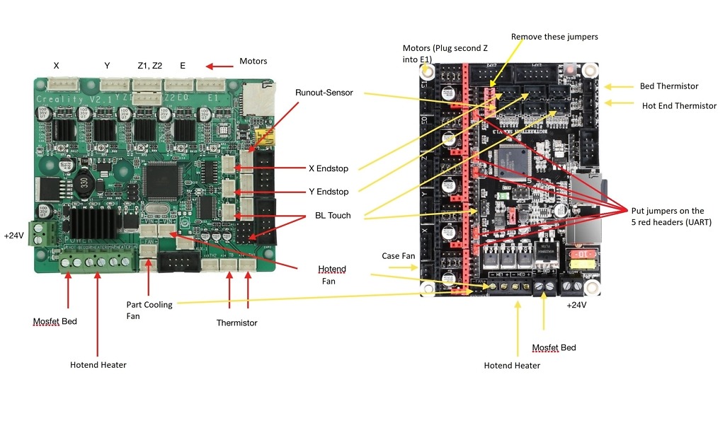
Remove the board, and mount the adapter plate you printed earlier, then attach the SKR1.3 to the mounting plate. (You may at this point find it easier to connect the blue USB cable and sdcard extender before mounting as space is tight!) Note, when mounting the end-stop plugs in the SKR you will need to carefully cut off one of the lugs so it can fit. Looking at the diagram above, they connect to the two rightmost pins in the relevant sockets.
Attach all the cables as per the diagram above. Remove all the jumpers from under the Drivers:
and I had to insert jumpers like this for the TMC2209s to be able to be controlled in UART (one in each driver socket)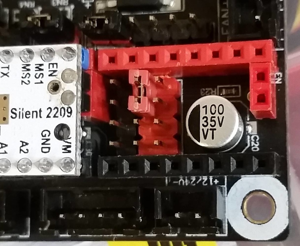
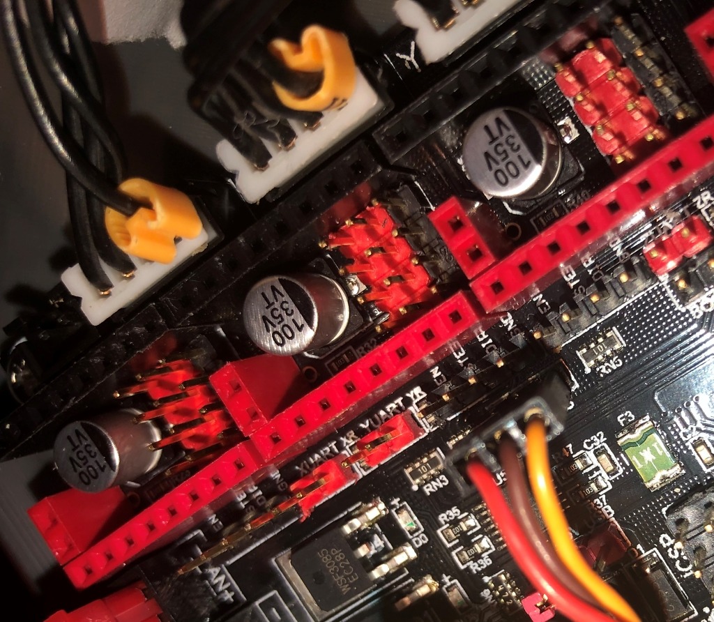
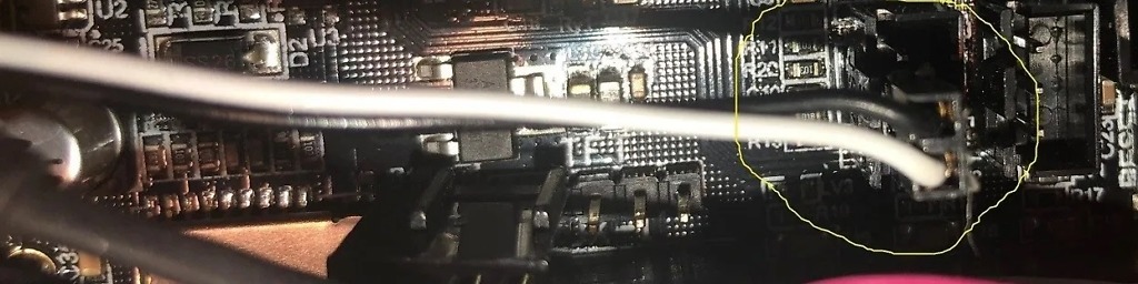
Next, to enable UART we need to add some more jumpers as shown here: (Note, don’t forget the one for E1 not circled in this picture)
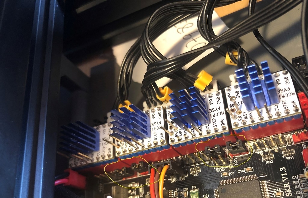
Insert the stepper drivers, taking care to note the polarity, and carefully mount the heatsinks.
The BLtouch wiring is pretty straight forwards
Pay attention to the order of the wires:
The two wires from the bltouch need to go into the bottom z endstop pins like this:
Screen Wiring
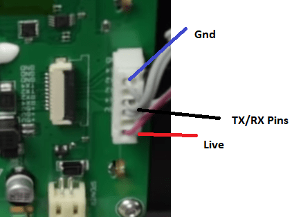
The screen wires to the single row of TFT pins on the SKR:
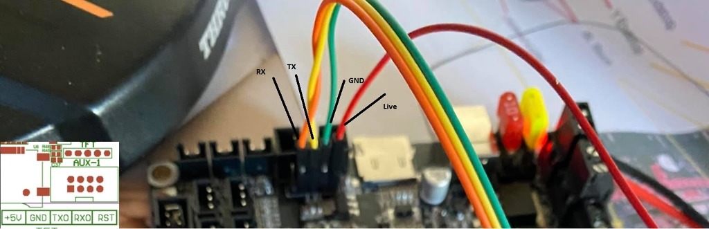
on the screen the two outside pins are labelled for ground and power, the 2 inner pins are TX and RX. The TX on the display goes to the RX on the board, and the RX on the Display goes to the TX on the board. I got the TX RX pins the wrong way around on the first attempt (this does not harm it by the way) and simply had to sway them around.
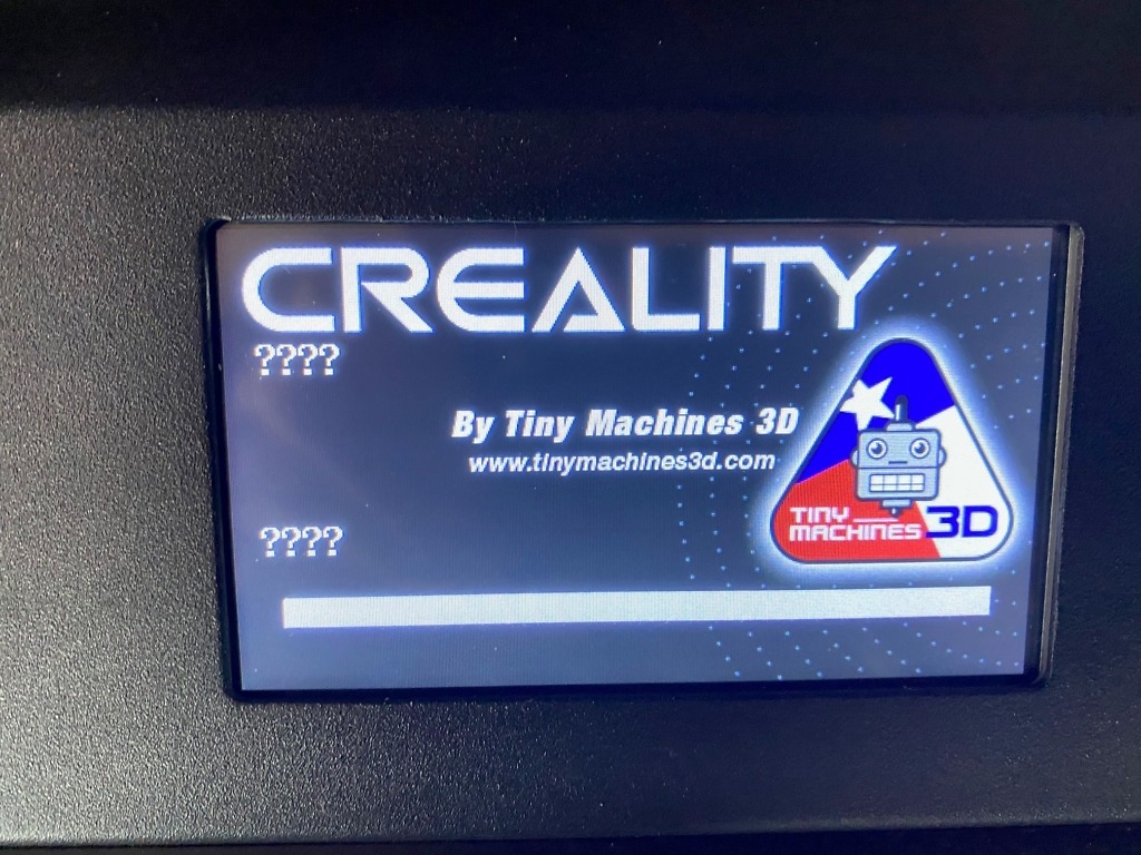
To upgrade the screen, you need to copy the DWIN_SET folder from the screen firmware (only that folder and its contents, not the rest of the files in the zip file) to an SD card formatted as FAT32 4k clusters, then insert the card into the touch screen board Power cycle your printer and the touch screen will update itself. Once the update finishes, power cycle the printer again. The SD card must be formatted using FAT32 and 4k sectors otherwise it wont read it (Max 2gb I think – you may need to partition your card)
Note, the screen won’t work correctly until we have done the rest of the steps below and loaded the correct firmware on the SKR 1.3.
You will probably see a screen like this for now:
Firmware
Next unpack the Insanity Automation Marlin folder to the root of your drive (we need to keep the directory depth as short as possible, or we will get errors!)
open VSCODE and make sure you have platformIO set up, and open the extracted folder
We are going to make some changes to Configuration.h first:
uncomment these lines:
#define MachineEnder5Plus
#define BedDC
#define ABL_BLTOUCH
#define ABL_BI
#define MelziHostOnly // Enable this to turn off local SD support and instead prioritize options for Octoprint or USB
#define SKR13 // 32 bit board - assumes 2208 drivers
#define SKR_2209
#define SKR_UART // Configure SKR board with drivers in UART mode
//#define SKR13_ReverseSteppers // Some users reported directions backwards than others on SKR with various drivers.
#define DualZ // Uses 5th driver on CRX or SKR boards as Z2
#define MeshStd
#elif ANY(MachineCR10Orig, SKR13, SKR14, SKR14Turbo) && DISABLED(SKR13_ReverseSteppers)
  #define INVERT_X_DIR true
  #define INVERT_Y_DIR true
  #define INVERT_Z_DIR true
Replace the Filament runout section with this (lines 2043-2083 currently, but check!)
#define FILAMENT_RUNOUT_SENSOR

#if ENABLED(FILAMENT_RUNOUT_SENSOR)

  #define NUM_RUNOUT_SENSORS   1     // Number of sensors, up to one per extruder. Define a FIL_RUNOUT#_PIN for each.
  #define FIL_RUNOUT_INVERTING false // Set to true to invert the logic of the sensor.
  #define FIL_RUNOUT_PULLUP          // Use internal pullup for filament runout pins.
  //#define FIL_RUNOUT_PULLDOWN      // Use internal pulldown for filament runout pins.
  // Set one or more commands to execute on filament runout.
  // (After 'M412 H' Marlin will ask the host to handle the process.)
  #define FILAMENT_RUNOUT_SCRIPT "M600"
  // After a runout is detected, continue printing this length of filament
  // before executing the runout script. Useful for a sensor at the end of
  // a feed tube. Requires 4 bytes SRAM per sensor, plus 4 bytes overhead.
  //#define FILAMENT_RUNOUT_DISTANCE_MM 25
  #ifdef FILAMENT_RUNOUT_DISTANCE_MM
    // Enable this option to use an encoder disc that toggles the runout pin
    // as the filament moves. (Be sure to set FILAMENT_RUNOUT_DISTANCE_MM
    // large enough to avoid false positives.)
    //#define FILAMENT_MOTION_SENSOR
  #endif
#endif
Now we need to make some changes in configuration_adv.h
#define E0_AUTO_FAN_PIN P2_04
And finally in pins_BTT_SKR_1_3.h:(this is in Marlin\src\pins\lpc1768\)
//
// Filament Runout Sensor
//
#ifndef FIL_RUNOUT_PIN
  #define FIL_RUNOUT_PIN                   P1_29
#endif
On the left of VSCODE, you will see some icons, select the alien fave (PlatformIO) and look at the ‘Project Tasks’
Scroll down and expand the env:LPC1768 section
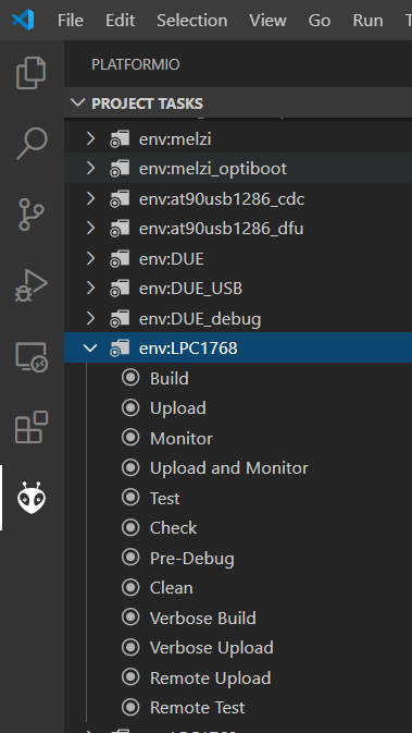
Click on Build to compile the firmware if successful, the terminal window will show this:
DUE                       IGNORED
DUE_USB                   IGNORED
DUE_debug                 IGNORED
LPC1768                   SUCCESS   00:00:17.251
LPC1769                   IGNORED
STM32F103RC               IGNORED
STM32F103RC_fysetc        IGNORED
STM32F103RC_btt           IGNORED
STM32F103RC_btt_USB       IGNORED
STM32F103RC_btt_512K      IGNORED
STM32F103RC_btt_512K_USB  IGNORED
STM32F103RE               IGNORED
STM32F103RE_btt           IGNORED
STM32F103RE_btt_USB       IGNORED
STM32F4                   IGNORED
STM32F7                   IGNORED
ARMED                     IGNORED
STM32F103VE_GTM32         IGNORED
STM32F103VE_longer        IGNORED
mks_robin_mini            IGNORED
mks_robin_nano            IGNORED
mks_robin                 IGNORED
mks_robin_pro             IGNORED
mks_robin_lite            IGNORED
mks_robin_lite3           IGNORED
jgaurora_a5s_a1           IGNORED
STM32F103CB_malyan        IGNORED
chitu_f103                IGNORED
STM32F401VE_STEVAL        IGNORED
FLYF407ZG                 IGNORED
FYSETC_S6                 IGNORED
STM32F407VE_black         IGNORED
BIGTREE_SKR_PRO           IGNORED
BIGTREE_GTR_V1_0          IGNORED
BIGTREE_BTT002            IGNORED
teensy31                  IGNORED
teensy35                  IGNORED
esp32                     IGNORED
linux_native              IGNORED
SAMD51_grandcentral_m4    IGNORED
rumba32_f446ve            IGNORED
rumba32_mks               IGNORED
include_tree              IGNORED
================================================================================================ 1 succeeded in 00:00:17.251 ================================================================================================

Terminal will be reused by tasks, press any key to close it.
Your firmware will be in Marlin-CrealityDwin_2.0\.pio\build\LPC1768\ called firmware.bin (check the timestamp on it to make sure!)
copy this to the MicroSD card, place in your board and power on the board, wait a couple of minutes to finish updating the board.
Cycle the power, and you should now have a working screen, with Marlin 2.0 on your SKR, running 2209s in UART mode (No need to set VREFS) and enjoy the silence!
Hello Jimmy, thanks for the post regarding Ender 5 Plus SKR BTT.
I face to the same problem, I have Ender 5 Plus, but with BTT SKR mini E3 V2 and I decided to keep original screen. Unfortunately it’s doesn’t work properly when all is updated. I can move X-Y-Z, warm-up Bed + Hotend correctly but no auto-home and leveling.
When I try to flash the screen, I see all files copied success but the screen keeps original menu from creality. I can’t have Tiny Machine screen menu, maybe my problem is here.
Do you have any idea? Is there only the DWIN_SET folder to update on the screen, nothing else?
Thanks!
Did you make sure the microSD card was formatted as Fat32 4k sectors? (It is important to use 4k sectors or the screen wont read the card!) and which screen firmware did you use?
Hello, thanks for the reply. I’m not sure 100% I formated 4K, I will confirm this and try again.
For the firmware I used the link on your page (https://github.com/InsanityAutomation/Marlin/blob/CrealityDwin2.0_Bleeding/CR-XABL_Screens_V2Rev2.7z).
You think is the correct one?
For the main bord, SKR mini E3 V2 I took this firmware: https://github.com/DodgeDeBoulet/Marlin
If you have other links I take it.
Thanks!
The screen firmware has to match the marlin firmware, you may need to use the insanityautomation one I linked to in the post
@Bxlcity Tony any update?
@Jimmy White if the screen work and you can see what you doing, why to flash it? Is it just for better look?
No, the screen won’t work with the tiny machines firmware unless it’s been flashed. It also gives you more options
I have no option to format SD card with FAT32 and 4K cluster. It means 4k cluster is reserved to FAT partitions.
But someting went kinda OK if I formated to to 512kb
You can use MiniTool Partition Wizard to format 4K clusters
It allows to format FAT32 with 512 bytes or 1024 bytes.
With 512 i see it writing? 9 different files – Code .LIB .HZK .BIN ..DZK .ICO .WAV .BMP but everywher is :0000
Writing isn’t the problem, the screen requires a 4K cluster size to be able to read it properly.
I’d try that program but it not allows to format card with fat32 and 4k cluster. With exFAT or just FAT there is no problem to get 4kb cluster.
You could try rufus, I think that supports it
Rufus also have only 512b and 1024b for FAT32…(no 4kb there)
Assuming… there is no way to format SD card with fat32 and 4k cluster so all above is not possible to perform.
Or the procedure looks different than that.
What size sd card are you using? If it’s too big a partition you won’t be able to do 4K clusters
128Mb. – is it? Smalest I have right now.
Im getting my k’s mixed up.. it’s 4096k cluster size see https://www.reddit.com/r/ender5plus/comments/g5izw0/anyone_running_the_tiny_machines_firmware_on_your/?utm_source=share&utm_medium=ios_app&utm_name=iossmf
Hi again. I just confirm that my card is ok be couse I’d try to flash my display with brand new Sandisk card… so result is as above:
9 different files – Code .LIB .HZK .BIN ..DZK .ICO .WAV .BMP but everywhere is :0000;
after all no changes on display at all.
Download Rufus:
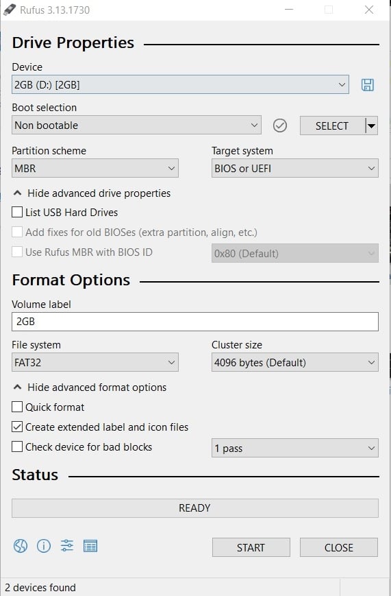

https://github.com/pbatard/rufus/releases/download/v3.9/rufus-3.9.exe
Format as 4k cluster:
The screen wont read the card properly if it isn’t 4k cluster size. You may need to partition your card down to 2Gb to get the 4096 cluster size
Hi again. So lady from DWIN wrote to me that i can format SDcard in MS DOS 🙂 Bulls#it.
I saw your photo with Rufus… so I can format my BRAND NEW 3rd SD card with no problem with standart Windows BUT it MUST be 2Gb card.
Probably 1Gb will be also ok.
And flashing process went ok. Finally !!
Glad you got it sorted! 🙂
Link to Rufus you attached is 3.9.1624 version and does not format cards I have to 4k cluster.Even 3.13 i found have no 4k clusters format…
I have 128Mb and 32Gb cards now.(smalest they had in electronic shop near me.)
I have no 2Gb. Maybe that is the problem.
So the smallone will format to with 512b and 1024b clusters and 32Gb will format from 8192 and above.
Or another maybe problem – I have win7x64.
I’d contacted with DWIN company and I have some answers. I’ll post results.
You can add in this description that the SD card MUST be 2Gb (maybe 1Gb or 512 Kb will work also) but not bigger.
Other cards can NOT be format with FAT32 and 4096 cluster.
Hello… Do you need the 2209 drivers for this to work? If you can use the 2208’s do you still need to change the jumppers?
Hi, you should be fine using TMC 2208s, however take a look at https://www.makenprint.uk/3d-printing/3d-printing-guides/skr-v1-3-setup-guide/ for setting up the 2208’s in UART mode on the board
I upgraded my ender 5 plus with the skr v1.4 turbo board and kept the stock screen. I flashed the screen with file in the link ‘screen firmware’ and nothing happened. When I power on the machine the display doesn’t even light up.
Hi Rob, if nothing happened when you flashed the screen, likely it hasn’t flashed – you should at least see a progress bar. Just to check, you were using an SD card formatted as Fat32 with 4k clusters? the cluster size is important, and you may have to re-partition your SD card as larger cards wont accept a 4k cluster size. Just create a 2Gb partition on the card, and format it as Fat32 4k clusters.
Also, you will need to use the matching insanity machines firmware on the SKR1.4 for it to work with the screen correctly.
Good luck 🙂
Yes I created a 1GB partition on a 8GB card and formatted it at FAT32 with 4096 allocation. I put the Dwin folder on the card and got nothing. I just got a new 2GB card I’ll try it too.
So I guess my new card is 8GB too. Tough finding a 2GB card nowadays. Put a 1.95 GB partition on it and formatted to FAT32 4096 and got nothing.
Can you share the file and folders on the card? I’ll see if I can spot anything obvious
Great Post!
But a new version of Marlin was already developed.
Is it possible to make my own firmware to SKR Pro 1.1 board and just flash the firmware with the DWIN from above and connect it to the board or are there any other changes in the TM firmware too ?
You write the two firmwares have to match – I don’t understand, please explain…..
Please help to use the stock screen, I don’t like the SKR screen….