

It’s a well-known fact that watching too much TV, especially in the dark, puts a strain on your eyes. There are many bias (or ambient lighting) systems out there for TVs and monitors, most of which rely on an HDMI input in order to capture the image before it is sent to the screen. Obviously, this is not much use with modern smart TVs that have a plethora of applications built in such as Netflix, Amazon Prime, BBC iPlayer, PLEX etc.
I started to hunt for an alternative solution and came across an excellent piece of software written by Waldo Bronchart, which he has written up here
This uses a Raspberry Pi, a USB camera and some WS2801 LEDs. The software captures the image from the USB camera, detects the colour at the edges of the picture and drives the LEDs to match. It even has a nice little companion app that allows you to draw a trapezoid around the region of the image the camera captures in order to accurately define the edges of the screen and adjust various camera settings (Gain, saturation, brightness, contrast etc). More on this later. for now, lets look at the parts list required: (All parts below are the actual ones I used, feel free to try different ones, but pay attention to the power requirements of the LEDs)
A power socket: adaptare Adapter DC Barrel Jack Socket Power Terminal Block (Pack of 1, 5.5 x 2.1 mm, 93522![]()
 A Power Supply: Tesfish 5V 8A LED Strip Power Supply Converter Adapter 5.5×2.1/2.5mm For WS2811/2801 LED String Light
![]()
Some Wire: 18 Gauge Electrical Wire , 18 AWG Silicone Wire Hook Up wire Cable [10 ft Black And 10 ft Red] Soft and Flexible 150 Strands 0.08mm of Tinned copper wire High temperature resistance![]()
LED Strips: BTF-LIGHTING WS2801 5050 SMD RGB 32Leds/m 96leds Addressable Individual Waterproof IP67 Black PCB Pixel Strip Light DC5V 3M 9.8ft![]()
USB Camera: Logitech C270 Webcam HD High-Quality Video and Audio Technology – Black![]()
And of course, a Raspberry Pi (i used a model 3) minimum 8Gb SD Card, some tools – wire strippers, soldering iron, solder, volt meter etc.
I found a 3m roll of WS2801 LEDs is perfect for a 42″ screen – you may need more or less than I had, so measure up first!
Preparing the SD card
You’ll need at least 4GB free space on the card. I managed to make this fit on an 8Gb card by removing some of the software installed with the Pixels distro.
First of, head off to raspberrypi.org and download the Pixels image and write this to your card. Boot the Pi and be sure to enable SSH, and the SPI interface.
You can find my fork of all the code here
SSH to your PI, and run
wget https://raw.githubusercontent.com/jimmyeao/AmbientLightServer/master/install.sh
Run it with
sh install.sh
This will remove the wolfram engine and libreoffice in order to make some room (8gb card minimum required) and install all the pre-requisites, and compile all the required software. This is going to take a long time, just over 3 hours on a raspberry pi3!
once finished, look at HardwareConfig.h in the ~/AmbientLightServer directory to see how to set up your LEDs (you will need 2 strips).
After editing this file, you will need to re-compile just the AmbientLightSever application, these only take a minute or so. You must be in the AmbientLightServer directory, then use this command:
make -j4
the -j4 tells the compiler to use all 4 cores. The other option you may wish to change is the starting LED position. you can find this in the TrapezoidSampler.cpp file at line 43. don’t forget to recompile if you change this setting!
That’s it for the Raspberry Pi software, next let’s move onto the hardware. For this project, we cut the LED strip in half to have two equal lengths. you should see the point at which they can be cut easily enough – there will be 2 sets of 4 solder pads annotated +v d1 c1 and gnd. Cut cleanly between the two rows.
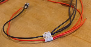
The image on the right shows the power wiring – 2 short positive and ground wires to power the pi, and 4 longer wires, 2 live and 2 ground, to power the LED strips. be careful measuring the lengths, they will need to stretch from the Pi (which I mounted in the centre rear of the TV) to the top and bottom of the screen, or opposite corners, depending on if you changed the start position in TrapezoidSampler.cpp. At this point, I plugged the power supply in, connected it to the socket and checked the polarity! You will also need another 4 identical lengths of wire for the data connections.
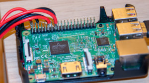
Solder the power wires from the PSU connector you have made to the Pi, pins 2 (Live) and 6 (Ground). Solder the other 2 pairs of power to the LED strips, taking care to note the polarity, and make sure you solder to the beginning of the strip. (Mine had arrows showing the direction of flow)
Next is the data and clock wires. may attention to the LED strip – it should be marked C1 and D1 for clock and data respectively. If you see C0 and D0, chances are you are at the wrong end of the strip.
These need to be soldered to the PI – use these pins for one strip – Pins 11 (data) and 12 (clock) for the first strip, and pins 15 (data) and 16 (clock) for the second. You can find a handy reference here showing the pin numbers.
Now DOUBLE CHECK YOUR WIRING!! Make sure there are no shorts anywhere. Hook up the camera to a USB port and power and boot the Pi. with mine, some of the LEDs light up on boot up. Ignore it for now, we just want to check everything works
SSH into the Pi, cd to the AmbientLightServer directory and run
sh run.sh
The software should startup, then start reporting how many FPS it is receiving from the Camera.
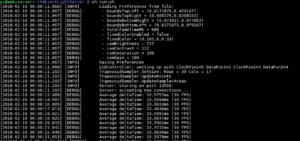
The LEDS should all be lit, and change colour as you move the camera around. If not all of the LEDs are lit, check your config in Hardware.h and make sure the number of LEDs etc are set correctly.
The next thing you are going to want to do, before mounting the LEDs, is to use the companion application to define the screen area in the captured image. For this, I used a windows 10 PC with Python and a copy of AmbientLightPyClient (https://github.com/waldobronchart/AmbientLightPyClient).
You will need Python installed to C:\Python33 , cx_Freeze used for compiling the client into an executable and PyQT4
Install Python and check the options against those set below

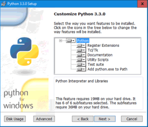
Next install CX_freeze, with all the default options. The install PyQT4 with the defaults.
Download and extract the AmbientLightPyClient Open a cmd window in the directory and run build.bat
This will create a directory called build, and within that exe.win32-3.3 and in there you will find the Ambilight.exe
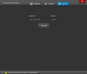
Make sure your raspberry pi is running the Ambient Light Server and launch the Ambilight.exe.
Go to the Server tab, and enter the IP address of your Pi and click connect
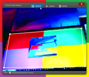
Now go to the Sampler Tab, and after a short delay you should see the image captured by the Pi, and a bounding box with corners you can drag. To set this up, I created a test card
Use this to figure out the orientation of your LEDs before you attach them to the back of the screen!
You only need to run the client if you move the camera, or want to adjust the colours etc on the colour tab – AmbientLightServer saves the preferences locally on the Pi.
Now everything is working, go ahead and mount the LEDs and the Pi to the rear of the TV, and find a suitable location for your camera. (Hint, you can get clip-on wide angle lens adapters from eBay, allowing you to position the camera closer)
Having this working is great, but it’s a bit of a pain to have to SSH into your Pi to turn it on and off all the time, so I have a few more steps.,. I purchased a smart plug for the power supply and installed some additional Python modules on the Pi so I could write a simple script to turn off the LEDs when I had finished with them.
Let us install the required python and libraries:
sudo apt-get install git build-essential python-dev
cd ~
git clone https://github.com/adafruit/Adafruit_Python_WS2801.git
cd Adafruit_Python_WS2801
sudo python setup.py install
now lets create a script to turn the LEDs off:
cd ~/AmbientLightServer
nano off.py
and enter:
from __future__ import division
import time

# Import the WS2801 module.
import Adafruit_WS2801
import Adafruit_GPIO.SPI as SPI


# Configure the count of pixels:
PIXEL_COUNT = 47
# The WS2801 library makes use of the BCM pin numbering scheme. See the README.md for details.

# Specify a software SPI connection for Raspberry Pi on the following pins:
PIXEL_CLOCK = 22
PIXEL_DOUT  = 23
pixels = Adafruit_WS2801.WS2801Pixels(PIXEL_COUNT, clk=PIXEL_CLOCK, do=PIXEL_DOUT)

# Alternatively specify a hardware SPI connection on /dev/spidev0.0:
#SPI_PORT   = 0
#SPI_DEVICE = 0
#pixels = Adafruit_WS2801.WS2801Pixels(PIXEL_COUNT, spi=SPI.SpiDev(SPI_PORT, SPI_DEVICE))

# Clear all the pixels to turn them off.
pixels.clear()
pixels.show()  # Make sure to call show() after changing any pixels!

PIXEL_CLOCK = 17
PIXEL_DOUT  = 18
pixels = Adafruit_WS2801.WS2801Pixels(PIXEL_COUNT, clk=PIXEL_CLOCK, do=PIXEL_DOUT)

pixels.clear()
pixels.show()  # Make sure to call show() after changing any pixels!
press CTRL+X then Y to save
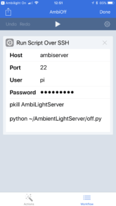
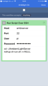
I also use an app called Workflow on iOS to create two buttons that would effectively SSH into the Pi and run start and stop scripts. If you are an Android user, take a look at SSH Button
This is how my worklows look under iOS:
Thats it. Please feel free to leave any questions or comments below.
Hi! I really appreciate your effort! The idea is great and the installation based on your guide was very smooth until i reached the color setup. For an unkown reason the blue color is shown green and the green color is shown blue. Also yellow is switched with violett and vis versa. Only red seems to be correct.
Do you have any idea what went wrong or where i can switch the color channels?
With best Regards,
Peter.
HI Peter,
Thanks for the kind words. It sounds like the strands are mixed up, I’m out at the moment but when I get a moment I’ll have a quick scout through the code and see if I can see anything obvious to change like direction etc
I think you can dramatically simplify your install.sh … recently I’ve successfully built the AmbientLightServer with these packages:
sudo apt install git libjansson-dev liblog4cplus-dev libboost-dev wiringpi libopencv-dev libopencv-dev
sudo apt install libboost-thread-dev libboost-date-time-dev libboost-system-dev libboost-iostreams-dev
sudo apt install libboost-timer-dev
BTW, I’ve changed my HardwareConfig.h and LEDController.cpp to only talk to one PIN as I haven’t cut my WS2801 into two strands.
Regards
Michael
Thanks Michael, can you post up your config files as well? I’ll get another strand of leds and update my write up..
Hi. Love your project.
Would a WS2812b (without the clock) also work?
Sadly not, the only way I have seen these work is by disabling the sound driver and using the sound chip as a clock – this would mean quite a rewrite to make it work I think.
Okay. AliExpress to the rescue. Has somebody successfully compiled the client on Macos? My Windows-System did the job, but the app´s Window is tiny und locks up after “timeout”. (Wrong IP for the server…)
…seems as if one has to define the ip before compiling… “preferences.py”…
I hope this thread is still alive! I was able to get all the way to receiving a frame capture on the sampler in the python app. I’ve been having trouble trying to figure out how to get the LED connection up and running. Is there any wiring diagram of how the LED strips should be connected?
Thank you!
Hey,
I started on a project like this and can’t get the program to compile on raspbian buster lite.
These are the 2 errors:
/usr/bin/ld: /tmp/ccYIEBbn.o: undefined reference to symbol ‘cvCreateCameraCapture’
/usr/bin/ld: //usr/lib/arm-linux-gnueabihf/libopencv_videoio.so.3.2: error adding symbols: DSO missing from command line
Was wondering if you can provide additional images of the soldering ( actual pins ).
Do you think this project would be doable in a node js environment?
The raspberrypi.org website does not list an OS called “Pixels”. It seems you need to simply download “Raspbian”, which probably comes with a GUI called “PIXEL”. I hope I understand this right.
Pixels is their desktop – read more here https://www.raspberrypi.org/blog/introducing-pixel/
you can use raspbian light as well if you don’t need desktop.
I finally managed to make things work. Had a lot of troubles with compilation of opencv. At the end moved to a newer version.
However, I’d like to say a big thank you to you Jimmy. It was a nice time.
P.S.this webcam might require additional power. Some people propose to use externally powered usb hub.
Glad you got it working 🙂
I tried this with my Raspi Zero (v1.3 – no Wifi):
TLDR: it does not seem to work.
After initiating the first real command that is supposed to take 3 hours on a Raspi 3 (“sh install.sh”), the Zero went on doing stuff. The terminal window had updated every now and then. But after 36 hours I turned off my host computer which apparently killed the process, even though that USB port is always-on. Now the Zero won’t boot (at least with SSH over USB) with the installed SD card system. I guess something is corrupted in the file system.
Therefore I suppose that you need at least a Raspi 2. Too bad. The Zero would be ideal IMO, because it costs only 5 bucks and is super small.
Yes, the Pi Zero does not have enough grunt for this task, I wouldn’t attempt it on anything less than a Pi3B..
Hey Jimmy,
I was wondering if I can use sk9822. It has a clock pin but has a different pin layout. Would I be able to use it?
Hi,
to be honest, I am not sure, in theory you should be able to – you would have to find the correct libraries (The sk9822 is a clone of the APA102 I think) adn possibly modify a few lines of the code. They look interesting and may actually be better than the ones I am using. If I ever get time, I may grab a set and try them out 🙂
Hi,
Is this project still active? Been trying to compile it for days on both Debian Buster and Arch on a Raspberry 3B, it doesn’t work. Seems like it’s missing headers for opencv.
In file included from main.cpp:15:
CameraController.h:4:10: fatal error: opencv/cv.h: No such file or directory
#include
^~~~~~~~~~~~~
compilation terminated.
I haven’t touched it for a while, I’ll take a look over the next day or two, think I have a spare pi somewhere
Any updates?
I’ve ordered another PI so I can test this, my spare was an original model PI! if you can bear with me a day or two, I can get it tested against the latest OS
Ok, found the issue, opencv has moved from Sourceforge to github, and also the newer GCC++ compiler has a known issue related to a change in the format of g++ -dumpversion. Fixed the script, this has given me some new errors, opencv isn’t compiling as expected now so looking at that today
Ok, the script has been fixed, tested with the latest Raspbian Lite image on a Pi 4
Nice, thanks.
Fantastic article. I just set this up with a pi 4 and a C615. Is there a reason the light strip must be cut in two? Can it be configured with a single strip? I’m using a 160 led 5 meter strip.
Hi, glad you liked it 🙂
I use two strips to prevent power and signal drop off, but in theory you could use one strip
Hi Jimmy,
I have gone through the code in great detail yet, but does the pi switch off when the tv does?
Hi Jimmy,
I haven’t gone through the code in great detail but does the pi turn off with the tv?
Hi Dan, it doesn’t, but if you use homeassistant /node red it shouldn’t be too hard to do
Cool, I’m a bit of a noob so i’ll do some googling into what these are and how they work . Would something like this work also? https://forum.libreelec.tv/thread/20247-how-to-turn-on-off-raspberry-pi-via-tv-usb-port/
Also, while I have you here, I’ll be running this on a 75inch tv , so i’ll need the widest angled camera lens i can find, would a fish eye Camera Pi be a good option? Or is it easier to go with a usb camera?
I haven’t tried with a Raspi Camera, likely would need some code changes but its worth a go.
Re the link, that looks interesting, that should do it, you will want to set up ambilight server to autorun on start also
Being that is is my introduction to raspberry Pi and I’m not a coder(I’m an IT teacher though and teach basic Python, so i have the capacity to learn), I think i’ll keep it simple and stick with the camera you used. I may have to be creative on how/ where to mount it since the screen is larger as well.
I’m looking at running a pi 4 model B and 5 meters of SK6812 RGBW LEDs as the only variants from what you describe on your build, so i’ll do my best to replicate where I can to save headaches.
Do you have any further information/suggestions about how you might use homeassistant /node red to power the Leds with the tv, so it’s “wife and kid” friendly? I’ll start with just getting it to work so no rush, but this is functionality i’ll be wanting down the road.
Hi Dan, it’s a big topic to consider (homeassistant and node red) but in essence, if your tv is a smart tv you should be able to set up homeassistant so that it can see whether the tv is on or off, and node red is the logic that can perform actions when the state changes, eg run an ssh script to turn off the leds or even kill the power via a smart plug. It’s a learning curve for sure, but doesn’t really need much programming experience, and there is a ton of stuff on the web and YouTube that goes into detail on how to set it up
I recently finished this project on a 75″. It was not for the feint of heart! The link to enable pi with TV would likely not work well for this project. This has an external power supply that would need to be controlled, not the pi iteself.
For a 75″ you will need a minimum of 5 meters. I’m doing 5 with one single wire setup (needed lots of c++ code changes), but still has some ‘noise’. Noise seems to be defined by random blinking. I used heavy wires (recommended in this post) to dramatically improve, but I’m thinking of splitting the wires into 4 (for power only, leaving 1 constant for data).
I wrote an Android App with casting capabilities to help configure and show off the TV, so if you’re an Android user I can share the APK with you when you complete the project.
For the camera, I have it on the ceiling, right above my head (about 10 feet). I’m using the Logicech C270. I tried 2 other cameras, and they didn’t work well with the software (didn’t have the right controls for calibration), so I’d stick with that.
The lights work amazing, but the rated lights that can be used by the PI directly are not the most powerful, and on a 75″, a lot is lost in the screen size. A brighter light + smaller TV would make a much bigger impact (but I don’t regret doing this at all).
Good to hear how you got it working, would you mind sharing your code changes or a link to your github repo (if you have one). Long strips do offer from power drop, so inventing power it intervals along the strip is a good idea.
Hi Joey,
I’ve actually just connected my 5M strip on to the default code and I get a lot of blinking. I only changed the number of LEDs and just disabled the update for the second strand. Just to see how it behaves.
Do you mind sharing your experience and maybe your code with me to help me out?
My e-mail is: Vo**********@***il.com
Hi Joey,
Wow some great advice here, thanks! I think i’ll focus on getting the LEDs working as a starting point before I tackle the power on/off functions. I have hope i can do it in code rather than needing hardware.
Is there anyway you could send photos if you decide to “split the wires into 4 (for power only, leaving 1 constant for data)” for reference? I’m thinking I will follow Jimmy’s guide in having 2 separate strips.
I’m i’ll have a few more questions as I begin the project, basically i’m waiting on shipping, but can’t wait to get started!
Oh! And I can’t wait to try the app!
Hello,
Thank you Jimmy for such a great & thorough DIY. Most of the other DIY’s on the web I’ve seen are incomplete, very unclear and/or not detailed enough for everyone. Much appreciated!
I finally got the chance to start this project. However, a friend gave me a new 8GB Ram Pie 4 they didn’t need. I am assuming this would work fine, correct? Or may even help.
Additionally the LED’s I got are the APA107’s, 60 leds/meter, same pcb as APA102, just with better PWM, which I am assuming would help the LED’s respond faster.
Could I use these APA107’s instead?? Any general thoughts on this??
Here is a link to them for reference:
https://www.amazon.com/dp/B07MDD191C?psc=1&ref=ppx_pop_dt_b_asin_title
All other parts I bought identical to yours above.
Thank you very much again Jimmy. Even the comment section was helpful as it clarified a couple of things. Again much appreciated…far as Bias lighting DIY’s, this is one of the best on web.
Hi, firstly, thanks for the kind words!
The pi 4 will be great for this project, and I see no reason why those leds would not work. – I would hook them up before cutting and installing them just to test first though!!
Good luck 🙂
Hi Jimmy,
Finally I’m starting this project!
I’m about to begin with the hardware. I have a 5m SK6812 RGBW Led Strip (for my 75inch tv)
https://a.aliexpress.com/_mtxl3Kt and as is shown on the 6th image in the link, I only have power, ground and data but no clock. Is there a way to still use these lights with this missing?
Also, is it possible to get a quick wiring diagram showing a complete picture of the correct wiring layout? Aside from the text description and image?
I just want to make sure that I’m understanding everything clearly and from what’s here I’m not confident as I’m more of a visual learner.
As always thanks for everything!
After reading https://tutorials-raspberrypi.com/connect-control-raspberry-pi-ws2812-rgb-led-strips/ and looking through the code, I’m thinking I’ll just order the. Correct LEDs and go from there to save time and headaches… The link also had great detailed tutorials on wiring LEDs to Pi’s…
Hello, great article! Is this still alive and up to date??
I have some troubles to light the LEDs. And to send the “livestream” from the Camerai to the Ambilight Programm on my Desktop PC.
Hi Philipp, I haven’t looked at for a year or so, but happy to try and help if you have a specific issue you can describe?