

Read part 1 here.
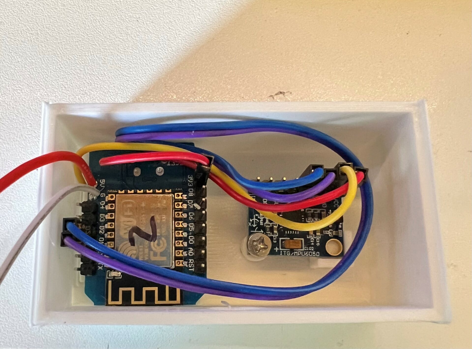
So, in part 1, I was going to use a multiplexer to grab the signals from the MPU6050 gyros. What I hadn’t realised is that these devices communicate over the I2C bus, which is only really meant for on board communications, and short distances. I had to ditch this idea, and instead each MPU6050 is hooked up to a Wemos D1 Mini (esp8266) running ESPHOME that can report the angle back to Homeassistant.
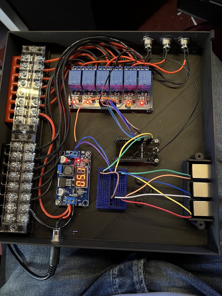
Work on the control box is coming along well, it has a 12v input, 2 busbars to feed the 6 channel relay (1 pair for each actuator) and a step down (buck) convertor to feed 5v to the ESP 32 and the Wemos D1 minis. (I used RJ45 connectors for these as I had a ton of spare cat5e)
Here is the 1st mock up of the control box:
You can download this case from Thingiverse here.
At the bottom, you can see a 12v input (I’m using a 12v 6amp power supply as my actuators are rated at 5amps max) – this feeds the busbars and a buck convertor.
The busbars feed the 12v to the relays and then on to the actuators themselves. The buck converter steps the power down to 5v and feeds the ESP 32, relay board control circuit and the Wemos D1s which in turn feed power to the MPU6050s.
These are the parts is used (Disclaimer: these are affiliate links, it costs you nothing to use, but I do get a small amount from these which helps pay to keep the site running)
| Busbars | https://amzn.to/3p0xEYt |
| 12V Connectors | https://amzn.to/3oV8eeG |
| Junction boxes | https://amzn.to/3vDMNCL |
| RJ45 Sockets | https://amzn.to/3JBVgfl |
| ESP32 | https://amzn.to/3JFxDmk |
| MPU6050 (Gyro) | https://amzn.to/3Jwee7b |
| 6 Channel Relay | https://amzn.to/3AuVhPc |
| Actuators | https://amzn.to/3d6wwjd |
| Wire | https://amzn.to/3dbSgKI |
| Buck Converter | https://amzn.to/3oVWfNV |
| 12v Power Supply | https://amzn.to/3QREviF |
The code for the ESP32 to control the relays, and the Wemos D1 minis controlling the MPU6050s can be found here https://github.com/jimmyeao/ESPHOME-SolarTracker/blob/main/solartracker.yml
This is what it looks like in HomeAssistant: (Note, the angles are odd as they are yet to be mounted!)
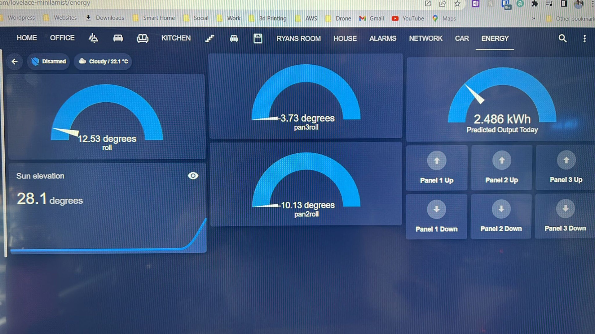
The relays are interlocked so that only one may be activated at a time, this is to keep the power draw down to within the spec of the wire and power supply used. I would encourage you to work out what you need for YOUR installation and make sure it is right – electrical safety is a must.
Still to come –
- automating changing the angle every hour when the angle is in a certain range
- adding a wind speed sensor to lower the panels if the wind picks up too much
- actual mounting of the panels, actuators and gas struts
- deeper dive into the code and automations
Stay tuned for part 3 🙂
1 thought on “I’m Going Green – Part 2”